
Once the immersion heater can be controlled via a Fibaro 3KW relay module, I can then schedule some scenes in Vera to automatically turn on the immersion heater at 6am for twenty minutes, so we have hot water when getting up.
Here you can see my new Immersion Heater device in Vera UI5.

My initial plan was just to wire in the Fibaro 3KW relay insert module in behind the immersion heater switch in the kitchen.

However my concern was that the immersion heater uses around 3KW and that the Fibaro relay module would be operating at its upper limits, so a safer and smarter solution was needed. I then thought about also using an additional more heavy duty relay and to have that one handle the heavy load and just have the Fibaro relay switch on and off the additional rely.
So I spoke to my new electrician friend Ahmer Mohammad, who is also a home automation enthusiast (his website "A Smarter Home"), and he also sells and installs Solar Thermal (hot water heating) systems via his renewables company "Solar Sparks", which is based in Leeds, West Yorkshire, England.
With his advice and installation instructions I was able to purchase a suitable relay and install everything and get it all up and running. I’d also like to thank user “RexBeckett” on the Micasaverde Vera user forums, who is one of the well known experts on there, for his input and advice on the project also!
DISCLAIMER ALWAYS SEEK PROFESSIONAL ADVICE FROM A CERTIFIED ELECTRICIAN FOR YOUR OWN INSTALLATIONS
Here is the wiring diagram I was working from, which was approved by the Electrician:

Here is a photo of the SSR and information about the terminals:

And here are the written instructions from the Electrician:
Use a junction box or heavy duty 20A connectors for the 'lives' as only 1 is coming out of the switch but you need to connect to 3 places.
same with neutrals as only 1 from switch but you need to connect to 3 places as well.
Live from switch connects to:
live in Fibaro
IN in Fibaro
on 1 of the output terminal in the relay
Neutral from switch connects to:
neutral of Fibaro
neutral of the relay (INPUT SIDE)
neutral of the immersion
OUtput 1 of the Fibaro connects to the Live of the relay INPUT side
Live of immersion connects to the switched out terminal of the relay
principle
turn switch on this acts as our isolator for this whole system so don’t need to turn mains off if ever need to change or alter Fibaro, relay or immersion
Fibaro becomes live and ready to accept z-wave commands
Fibaro will then turn the relay on or off
the output contacts of the relay will close or open respectively
when relay contacts closed the immersion is on
nice and safe as we previously discussed.
Parts I needed for the job:
1 x Fibaro 1* 3KW relay insert module (Note- these are now discontinued and have been replaced with the newer 1* 2.5KW FIBEFGS-212)

You can purchase Z-wave Euro devices from us directly, contact us to discuss your personal requirements and we can then offer bespoke discounted pricing.
1 x Solid State Relay which I purchased off eBay. You can buy these without the heat sink, I bought one that came with the heat sink.
Single Phase Solid State Relay SSR-40AA 40A 150-350V 24-480VAC w Heat Sink

Here is the specification of the SSR
Product Name
Solid State Relay + Heat Sink
- Model
SSR-40AA - Material
Metal, Aluminum, Plastic - Rated Load Current
40A - Input
AC 150-350V - Output
AC 24-480V - Total Size (Approx.)
8 x 5 x 8cm / 3.1" x 1.9" x 3.1" (L * W * H ) - Color
Black - Weight
190g - Package Content
- 1 x Solid State Relay
- 1 x Heat Sink

This is the old switch in the airing cupboard I replaced and don’t ask me why the walls in the airing cupboard are pink? I didn't paint them that colour!

1 x Single Dry lining box 35mm bought from Screwfix here.

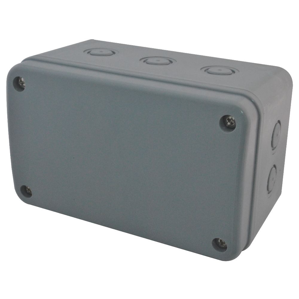
1x Electrical enclosure box 180 x 110 x 100mm from Screwfix here.
1 x 20A Junction Box also from Screwfix here.

I also needed some twin and earth socket wire.
Installation:
First step was to ensure that the switch for the immersion heater in the kitchen was turned off, to isolate the circuit upstairs in the airing cupboard. Then I started to remove the existing ON/OFF switch in the airing cupboard, that connects to the immersion heater at the top of the water tank via a flex cable.

I then knocked out a new hole in the wall for the new dry lining box. The cable you can see is the existing cable that comes from the immersion heater wall switch downstairs in the kitchen.

Here is the back of the switched fuse spur, I connected the existing cable in the wall to the Live and Neutral IN and the earth cable to one of the earth connectors.


I then added a short piece of new twin and earth cable to the Switched Fused Spur – To the Live and Neutral OUT and earth to the other earth connector. This cable will be fed back through the dry lining box and connected to the new 20A junction box that will be placed and hidden inside the stud wall.


Feeding the new cable back through the dry lining box.

Attaching the new cable to the Junction Box. Live, Neutral and Earth, the various connections needed as shown in the wiring diagram, will all come from this new junction box.

I then starting checking out the enclosure box, to see where it would be mounted on the wall and where I needed new holes in the wall for the cables to come through in to the box


My Dad always told me make sure its level!

I made two new holes in the wall behind where the enclosure box will be mounted.

I also cut out all the access holes of the box for air flow, as I was worried about how hot the SSR relay would get? The heat sink does get hot and you can’t leave your finger on it for too long!

In this picture you can see I have added two new pieces of twin and earth cable and looped them round in the two new holes and out through the larger hole for the dry lining box.

Next step was to connect the ends to the Junction Box.


As per the wiring diagram, I also needed one extra Live cable, so I also added a single Live cable from the junction box and looped it round to one of the holes in the wall, to go in to the enclosure box. I also at this point, wired in the neutral and earth cables from the immersion heaters flex cable in to the junction box, I don’t have photos of this step.
In this photo I have put the top on the junction box.

Next I mounted the SSR relay in to the box, I had to drill two small holes in to the base of the box and using some nuts and bolts secured the SSR in to the box.

I then cut the excess off the bolts with a hack saw.

I then pushed the junction box in to the larger hole to hide it in the stud wall and started to connect up some of the cables to the SSR relay.
At this point you really need to start following the wiring diagram, to work out which cables are connecting to where on the SSR and to the Fibaro relay unit.


I mounted the SSR upside down, which just seemed easier as far as the wiring was concerned.

Once I had completed all the wiring and triple checked everything, I turned back on the power and tested I was getting power to the various live cables with my little screw driver that lights up.

It was then time to add the new Fibaro 3KW relay to Vera. So I put the VeraLite in battery mode, pressed the plus button and then pressed the button on the Fibaro module three times.

Here is a picture of the SSR powered up the red light comes on.

Here is the completed installation, minus a bit of pink paint as I had to fill in and tidy up the wall around the fused spur.

In the Vera web UI I could then see two new _Appliance Modules devices has been added. One is a child device and the other is the father or main device.

The reason you get two new devices, even though its only a 1* 3KW relay is because:
“The child device is for the S2 input. It allows you to use it as an extra input which can be useful if you need some way to signal Vera with some state.
The S1 input would switch the output and thus control the SSR directly.”
As the child device isn’t needed in my setup I hid the device using the following method:
You can hide it using the command:
luup.attr_set("invisible","1",123)Replacing 123 with the device number. In UI5, this needs to be placed in Startup Lua. In UI7, it apparently sticks if run once in Test Luup code (Lua).

Thanks to RexBeckett for this information and solution.
Immersion Heater turned ON

House Power Usage when the immersion is turned ON.
(CurrentCost EnviR Energy Monitor integrated into Vera with the plug-in).

After installing everything and actually sitting down and using Vera to turn on the Immersion Heater and then watching the real time power consumption usage, I noticed something that looked odd.
I thought there might be a problem? After about 8 minutes of turning on the Immersion the wattage dropped from 3000 and something watts to 600 watts. I went upstairs to the box and the SSR was still lit up and powered on. Then several minutes later it had shot back up to 3441 watts. It would keep doing this as if the immersion heater was being turned on and off after so many minutes. I suspected that it must be a thermostat on the hot water tank but wasn’t sure. Both the electrician and our resident forum expert both confirmed it was likely due to the thermostat on the immersion itself inside at the top of the tank.
Here’s what RexBeckett said about it:
“Immersion heaters usually have built-in thermostats. These turn on and off to keep the water temperature fairly constant. Because they are physically close to the heater, they can cycle quite often even though the tank temperature does not change quickly. I would expect your energy monitor to show the change in energy use as the 'stat cycles.”
After leaving the Immersion turned on for twenty minutes or so I checked the water from the tap and it was nice and hot, so it was indeed all working perfectly fine!
Summary
I am very pleased with how this project turned out and I will now be able to schedule some scenes in Vera to automatically turn on and off the Immersion Heater early in the morning so the water is nice and hot for when we get up. We can now also turn on and off the Immersion heater using our mobile phones and tablets, even when outside of the house!
Here are a couple of screen shots of the new Immersion Heater device in the Vera mobile app Authomation HD.


Next and probably a more expensive job, find a plumber to sort out the central heating boiler properly.
No comments:
Post a Comment